Thursday, February 27, 2020

Air Cleaner

PROJECT 51: Air Cleaner. When I bought the MG, the original air cleaner and its twin-carb manifold had been discarded and replaced by individual breathers on each of the carburetors … and one of those was only half there. (These probably came off a later-model MG TF.)
Fortunately, I was able to find an original assembly on eBay. Un-fortunately, it appeared to have been left setting upside-down in a pile of wet leaves for years, as rust had eaten through the chrome and pitted the base metal on top.
Chrome would have been an extra-cost option on the top of the cleaner element when the car was new, so I decided to take it back to its standard black-paint finish.
I sandblasted the rust and the flaking chrome away, which also served to roughen the intact chrome so the paint would adhere. I then used several coats of primer and multiple applications of spot-putty to smooth out the pitting.
The bottom half of the cleaner (the oil sump) was not rusted, so it cleaned up easily. While stripping the paint, I did find two cracks in the sheet metal, which I welded back together.
After a few coats of hi-temp black paint the assembly looks pretty much like new.
Back in 1951, virtually all cars used "oil bath" air cleaners, meant to be cleaned and reused for the life of the car. Replaceable paper filters wouldn't become common until the early 60s. It was a very effective way to clean the air before going into the engine, and some off-road vehicles that get used in very dusty environments still use it. But it was a mess when you had to clean it.
Changing the oil in the sump was easy, but cleaning the collected dirt-and-dust-encrusted oil from the wire-mesh element could be downright dangerous! The owner's manual recommends that the element be "lifted out and cleaned in fuel" every 3000 miles. (I remember my father doing that, and then putting a match to it to burn away any residual gas and oil. Fun to watch!)
I don't want to soak my newly-restored parts in gasoline (for many reasons!), so I will be using a paper filter element for daily driving, and just put in the oil-bath element when I take the car to shows.


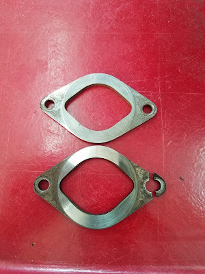
1 1/2 MG TF air cleaners.

Image from eBay ad.


Before.


Pitted chrome and base metal.
Note cracks at bottom of both clamping slits.
(Wetness is paint stripper.)

Shop manual pages showing how an oil-bath filter works.

Tops after.

Bottoms after.


Monday, February 24, 2020

Rock(er) On!

PROJECT 51: Rock(er) on! I finally got around to putting the new bushings in the rocker arms. I made a piloted mandrel with the intention of using my mill as an arbor press to push the old bushings out, but they wouldn't budge with the force I could put on the quill handles. I ended up using the vice, and had to lean pretty hard on the handle to make even that work.
The bushings have a very tight press-fit for good reason; they are designed with oil channels and an oil hole that must line up with the hole in the rocker. If the bushing were to rotate over time, it would shut off the flow of oil and the bushing would wear out very quickly.
After pressing in the new bushings, also in the vice, they had to be sized to match the new shaft. Pictured is one of the yard-sale adjustable hand-reamers shaving the bronze bearing material out to its proper size.
Assembled on a new shaft the rocker arm assembly is almost ready for installation. It will get new jam-nuts for the push-rod screws before it gets bolted to the head.


Attempt to use my mill as an arbor press.

Using the mill's vice as press.

Adjustable hand-reamer opening up a new bushing.

Old bushing.

New bushing showing oil channel and hole.

Old and new shafts. 
Nearly completed assembly. The adjusting screws
will get new jam-nuts.


Sunday, February 23, 2020

A Salute to Yard-Sale Finds

PROJECT 51: A salute to yard-sale finds. While I had the crankshaft out and on the bench, I checked the pilot bushing in its flywheel end. This bronze bushing keeps the front end of the transmission's main shaft in line with the crankshaft. Not surprisingly, it was worn considerably oversize. It was .022" larger than the shaft, when .002" would be the normal clearance. This was just normal wear for a car this age; not a Brutus thing, this time.
Fortunately, I happened to have a "pilot-bearing puller" sitting on the shelf. (Doesn't everyone?) This is an item I picked up at a yard sale probably more than a year ago, and likely paid $5 or so for it. I didn't have a need for it then, but I couldn't pass up the deal. (Can one ever have too many tools?)
It got me thinking about all of the yard-sale finds that I have been able to use in this project, so far. All of these were bought before I bought the MG, and some I have had for decades.
*Pilot-bearing puller (mentioned above) $5
*Large gear-puller (used to get the flywheel off the crankshaft) $4
*V-belt strap-wrench (used to hold pulleys for disassembly and reassembly) $5
*24" calipers (used to measure flywheel and ring gear) $30
*Pyrometer (used to check temperature of ring gear) $10
*Bike stand (used to hold ring gear during heating) $5
*Acetylene torch set (used to heat ring gear and other things) $35
*Hi-temp gloves (used to handle those hot things) $5
*Bench vice (used lots!) $40
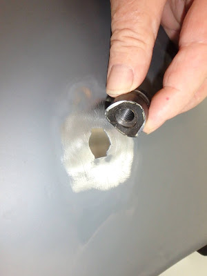
*Chassis punch (fender repair) $5
*Bushing reamers (will be used when rebuilding the front end) $15
*Gasket punch set (used to make new gaskets and cut masking tape to cover holes) $40
*Safety-wire pliers (used to twist the safety wire in numerous bolts) $10
*Large part-washing tub (used for many of the big engine parts) $2


Pilot-bearing puller.

Large gear puller.


V-belt strap-wrench.

24" calipers.

Pyrometer.

Acetylene torch and bike stand.

Hi-temp gloves.

Bench vice.
Chassis punch.

Bushing reamers.

Safety-wire pliers.

Gasket punch set.

Large part-washing tub.

Friday, February 21, 2020

The Right Way

PROJECT 51: The right way. Upon further reflection and on advice of counsel, I decided not to reuse the connecting rod that I removed and straightened in the last post.
Because this is not a high-revving powerhouse of an engine, the rod would probably have stood up in normal operation. But the consequences of that "probably" being wrong would be catastrophic. Below are a couple of photos of the carnage after a different MG engine "threw a rod," punching a hole in the side of the block, and even smashing the oil filter canister.
As Dave Cummings pointed out in a comment, the rod had been "compromised" when Brutus twisted it. Then, I added to that by twisting it back! I had become focused on the fact that I COULD straighten the rod, and lost sight of the fact that I SHOULDN'T.
But you can't replace just one connecting rod (or at least you shouldn't). They should always be kept as a matched and balanced set.
Fortunately, the local MG restoration shop in Mesa had a set of reconditioned rods on the shelf. They had been professionally sized, balanced, bead-blasted, and magnafluxed to find any microscopic flaws. Un-fortunately, that was another Brutus-induced $400 cost-overrun. (Still, that's a fraction of what it would cost if the twisted rod failed.)
So, feeling a little like a pit crew (pit person?), I took the engine completely apart, which included removing all of the piston rigs to get the pistons out and back in, replaced all the rods, and now have the bottom half of the engine back together, again. I just need to get some new cotter pins and I'll be back to square-one.
(My thanks to Dave, Scott, and Skip for your cautionary input!)


Rod through the side of an MG PB engine. 

It even took out the oil filter canister.
Old rods (dark) vs. reconditioned rods.


Back to square-one once the cotter pins are installed.

Thursday, February 20, 2020

Another Plot Twist

PROJECT 51: Another plot twist. In every other engine I've ever put together it is possible to install the assembled connecting-rod/piston/ring-set through the cylinder from above. Not so with the MG. The cylinders are too small in diameter for the big-end of the connecting rod to pass through them.
As a comparison, a Model-T's cylinders are 3 3/4" across. A 2020 Corvette's are 4 1/8". A 1968 Volkswagen Beetle's are 3 1/2". The MG's cylinders are a smidge over 2 1/2" in diameter. (The machine shop said it was like working on a four-cylinder lawnmower engine.)
As a result, the pistons must be inserted into the cylinders from inside the engine block before the crankshaft is installed. The pistons are then extended out the top of the block where the rings are installed. The rings are then compressed, and the piston is tapped back into the cylinder. It's a little convoluted, but it works.
With all four pistons installed, I set the crankshaft into its bearings and then torqued its three main-bearing caps in place. Next, I installed and torqued the connecting rod bearing caps, and then pulled the crank over a couple of times to make sure everything was free. I then set about inserting the cotter pins through all of the castellated nuts. That's when I noticed the Brutus twist.
Looking down into the block, I could easily see that the wrist-pin in the fourth piston was not lined up with the crankshaft. The connecting rod was twisted! I can only imagine that Brutus did it while trying to get the wrist-pin bolt loose. (Apparently the machine shop only inspected the large-end bearing diameters.)
In the 1952 shop manual, in the section regarding the "removal and replacement of the pistons," it mentioned that each piston could be removed from the block without removing the crankshaft, "if both piston and crank are manipulated in the proper manner." It would never have occurred to me to even try that if I hadn't read it there.
So, I disconnected the bearing cap, poked the piston out the top, removed the rings, and slid the piston back into the block.
It was like a three-dimensional brain-teaser puzzle, but sure enough, there was exactly one way of getting that piston out and I managed to find it!
Holding the piston in the bench vice with the wrist-pin caps I had made for removing the original bolts, I was able to get the twist out of the connecting rod using a 12-inch adjustable wrench clamped right next to the bearing-end of the rod.
Brutus must have clamped the bearing-end of the rod in a vice while cranking on the wrist-pin bolt. That would have forced the length of the rod to absorb all of the torque he was putting on the bolt before it finally broke free. Connecting rods are engineered to take straight push-pull loads; they never see torque in a running engine, so they are not designed to be strong in that direction.
Either the other three bolts were not as stuck as that one, or Brutus saw the error in his ways after his first attempt, but none of the other rods were twisted, thankfully!
Re-reassembly was pretty straightforward, after which I installed all of the (correct-size) cotter pins, and then added a few more of the accessories to the block, including a new timing chain. (Note the difference in its slack from the old one.)

Vintage piston-ring expander.

Piston-ring compressor.

The Brutus twist.

Brain teaser extraction.

Wrist-pin caps with old piston.

Caps clamped against ends of wrist-pin.

Coming together.

New timing chain.

Old timing chain that caused earlier bolt and cover damage.

Another Moss Innovation

PROJECT 51: Another Moss innovation. I made good progress getting the "bottom half" of the engine assembled, once I had the new lip seal retainer installed on the block. I put the new cam shaft into the block, along with a new set of bearings, and then I assembled the new pistons to the existing connecting rods, which were left at the machine shop for inspection, and deemed within tolerance.
Another great improvement that Moss Motors has made to MG's designs is to replace the hex-head bolt that clamps the small end of the connecting rod to the piston's wrist pin (gudgeon pin in Brit-speak). As designed by MG the hex-head bolt is almost impossible to get a socket on. Since it only needs 25-foot-pounds of torque to tighten, it could have been installed with a snug-fitting open-end wrench at the factory. Getting it out, many thousands of miles later, is another matter.
Although the bolt is continuously splashed with oil, it is separated from the combustion chamber by about two inches, and is shielded from that extreme heat only by the 1/2-inch-thick head of the aluminum piston. The result is that the oil turns to carbon over time, and locks the bolt in place, requiring perhaps three or four times the seating-torque to break it free. An open-end wrench will almost always round the edges off a hex-bolt under those circumstances. I needed Vice-Grips and a two-foot bar to break mine free! (I'm not sure what Brutus used when he removed the original pistons from the connecting rods, but I did get to deal with the results. Detailed in the next post.)
So, anyway, Moss's solution is to sell a set of socket-head-cap-screws (aka Allen screws) to replace the old bolts. As long as one has a metric hex-key socket to go on their torque wrench assembly is a snap, now. (Disassembly should be, too, but I hope I never find out.)
With all four pistons assembled, it was time to install them into the block.


New camshaft and bearings installed in block.

Old and new camshaft thrust bearing plates.

Original wrist-pin bolt on right; Moss's better idea on left.

Pistons ready to install.

Wednesday, February 19, 2020

Rear-Main Oil Seal

(Posted on FB 2/18/20)

PROJECT 51: Rear-main oil seal. Just behind the rear main-bearing that supports the crankshaft on all older cars is a two-piece oil seal that keeps the oil in the crankcase and away from the flywheel and the clutch, if so equipped. Two-piece seals were never a great idea, but were necessary because where the seal needed to sit, right next to the bearing, was a far smaller diameter than the adjacent hub where the flywheel was bolted on.
Over the years, with the advent of precisely-molded high-temp rubber compounds, these seals have gotten quite good, but back in the 1930's, when the MG's engine was designed, many manufacturers were using what amounted to a piece of clothesline rope squeezed against the polished bearing journal to keep the oil from seeping out. The concept was usually good for 50K miles or so, after which you had the engine torn down to replace the seals, or you lived with an oil leak. Most owners opted for the latter.
But the designers at MG had a better idea! They apparently reasoned that if there was no rear-main seal, it could never wear out. So, instead, they used a "slinger" disk behind the rear main-bearing to spin the escaping oil off into a collection cavity that drained back into the sump. Then, if any oil that got past that first line of defense it was forced to squeeze through a close-fitting gap to escape farther. And inside that gap was a shallow groove cut in a helix (called a scroll) that would pump that wayward oil back whence it came.
On paper this idea must have looked brilliant. But just in case it wasn't, they also added a 1/4" diameter hole in the bottom of the oil pan to let the leaked oil drain out. (This made it easy for MG owners to know where to put the drip pan on the garage floor, and someone even made a bolt-on drip pan.)
Eventually (probably in the 70's), someone at Moss Motors, one of the two main suppliers of MG spare parts, came up with an aftermarket design to install a one-piece lip-seal around the flywheel flange at the end of the crankshaft. This design actually IS brilliant!
Since the engine was never designed for this add-on, it is often necessary to machine the back surface of the rear main-bearing cap to allow the seal holder to fit, but after that the installation was reasonably straightforward.
I will also replace the two-piece seal at the front of the crank with a one-piece lip-seal, (a much simpler task) and if Moss's claims are correct, I won't need a drip pan! And that's quite a claim for an old British sports car!


MG's no-seal- rear-main oil seal concept.

The just-in-case-this-doesn't-work hole.


Aftermarket bolt-on drip pan. Like a "Depends" for your MG.

Moss Motor's better idea.

Amount that needed to be machined from bearing cap.

Machining the .100" from the cast iron bearing cap.

New seal retainer is sealed against the block with  hi-temp silicone.

New one-piece seal will be installed just before
the flywheel is bolted in place.